
I just saw a 57 Chevy station wagon for sale that has a 350 engine, with an alternator. HEI distributor and Ballast Resistor attached to the fire wall. Why would you need a ballast resistor with all those engine upgrades?

max46

Ballast resistor question
max46
Discussion starter
2,705 posts
·
Joined 2012
- Add to quote Only show this user
I just saw a 57 Chevy station wagon for sale that has a 350 engine, with an alternator. HEI distributor and Ballast Resistor attached to the fire wall. Why would you need a ballast resistor with all those engine upgrades?
536 posts
·
Joined 2007
When I converted from points to HEI and an alternator, I left
the resister on, but later removed it altogether. I don't think
you need resister with HEI & alt.
the resister on, but later removed it altogether. I don't think
you need resister with HEI & alt.
31,657 posts
·
Joined 2007
A true HEI will not work with a ballast resistor. Because the resistor is on the firewall and has some wires going to it, doesn't mean it's being used. It may be bypassed.
303 posts
·
Joined 2014
Sorry, but the info on an HEI NOT working with an HEI is just plain not true. The GM 1.80 ohm porcelain ballast resistor only drops the current down to about 11.5 volts, clearly enough to run an HEI, not well, but, they work.
Where do these old wive's tales and mis-informatoin all come from?
It does not matter if the vehicle has a generator, or alternator, all HEI's need full battery voltage, not resisted, but, they do start, idle and run adequately, not the best, with a resistor in place.
Friday: I am adding the info both myself, and my ignition system tech have both observed with an HEI. We both separately have measured all sorts of systems, including both big and small HEI's, and, at idle, the amperage use for hn HEI is at 4.5 to 5.0 amperes, and as the RPM's increase, the amperage draw DROPS, down to the 1.5 to 1.8 ampere level. Most radios use more amps than that. Now, this ISN'T a scientific study by any means, only two people with ammeters that can read the current draw, but, those ampere levels don
t indicate any real current draw from any HEI ignition system sufficient to cause trouble unless things like generators AND alternators are having charging problems.
I know GM designed the HEI system with the possibility that the alternator could fail, and the vehicle had to "limp home", so, even at lower voltages, so, they will still operate.
Willard Thompson
14,697 posts
·
Joined 2012
I realize this is an old thread but felt the info should be corrected. I believe if someone was measuring current to an HEI and it went down with an increase in RPM's, then they had a cheap meter that didn't read the pulsating current properly at faster frequencies (rpm's).
5,561 posts
·
Joined 2012
The purpose of a HEI (High Energy Ignition) system is to provide a hegher voltage spark at the plugs. It converts the available voltage into the higher voltage. If you put less that the 14 volts it's designed for into the system, you'll get less than the optimum back out. So, yes, the car with an HEI system will run with a resistor, but you're defeating the purpose of the HEI by doing so.
A far as why someone might leave the resistor mounted - it's a convenient place to hook up the windshield wiper motor without having to splice or find other connections. And, if you run a mini HEI to preserve an original look, the resistor adds to that look.
A far as why someone might leave the resistor mounted - it's a convenient place to hook up the windshield wiper motor without having to splice or find other connections. And, if you run a mini HEI to preserve an original look, the resistor adds to that look.
211 posts
·
Joined 2006
I've been dealing with the ballast resistor issue for a while, trying to decide whether to remove mine or not. I installed a Pertronix Ignitor and an Accel coil and left the resistor in place. According to a number of articles, including this one, from Hotrod.com, having the resistor in the circuit can decrease spark and hamper performance, so they recommend removing it. I'd also like to get rid of it because I don't like the looks of it. I moved it under the dash, but due to the design of the resistor, I'm not really comfortable with it under there.
14,697 posts
·
Joined 2012
You should be uncomfortable with it under there, they get hot. I've read different things about old and newer pertronix but I think you can get rid of it.
303 posts
·
Joined 2014
From all the amperage use testing I do on the systems I install, an HEI will run, not wellm, but, will run with a stock GM ballast resistor, or resistor wire. For a true HEI, feed it a full 12 volts.
Not every electronic ignition, especially the ones that replace points, should be run at a full 12 volts. With non-HEI systems, the ballast resistor should be left in place, and functional. in fact, a Mallory UniLite needs not just one resistor, but two, because the module want LESS voltage into them than other point replacement systems..
From the testing of use amperage for an HEI, the lower the rpms, the more amperage they use. The higher, the less. At idle, I routinely see 5.0 to 5.5 amps, after about 3,500 rpms, I see as low as 1.5 amps usage.
I asked this of my ignition tech, the best on this planet, why? The simple fact is, the more rpm's, the less time the coil has to absorb current, and the storage of current in the coil drops. At idle, there is, relatively, a lot more time for the coil to catch and hold volts, current, amperage, whatever you want to call it, and the more amperes are captured.
Want to test this, alligator clip an ammeter between the coil positive post and engine ground, run engine, change rpm's, read ammeter. If you say "no, that won't work, the charging system is still adding current", pull the fan belt off, and test again, it doesn't take a long time to read what goes on, certainly not enough time to overheat the engine.
Willard Thompson
14,697 posts
·
Joined 2012
OK what kind of meter are you using? If it's under $200 or so yes I believe that *you* believe everything you wrote. But that doesn't make it correct.
Just to double check myself I actually checked mine just now. The easiest way to do this without pulling any wires is to put the ammeter across the + side of the coil and the + post on the battery. Then start the engine, then turn the ignition OFF and the engine continues to run because it is being powered through the ammeter. Sure enough the amperage goes up with increase in RPM's. You can even set the meter to AC amps, since it's pulsating DC, it will still read amperage, although not correctly. But it will still increase with engine rpm.
In addition, when I first installed my MSD ignition sometimes it would start to miss at higher rpm's so I called MSD. The tech told me to check my voltage going to the coil. Sure enough it started out low and got lower as the rpm's increased. I had a poor connection or 2 powering my coil and as the rpm's
increased, so did the current, which made the voltage drop even more.
Oh, you also made a mistake above. If you put an ammeter between the + and engine ground, you will have a direct short to ground.
1,113 posts
·
Joined 2016
I converted to an Accel electronic distributor a few years back. The instructions said to bypass the ballast resistor because the ignition needed a full 12 volts to work correctly. I left it on the firewall and used it as a junction point only by hooking all the wires to the same end.
303 posts
·
Joined 2014
Yes, when the ignition is on in the car with an ammeter, there is NO grounding of any system.
However, you are correct, I err'd in that I said to ground the other end of the ammeter, when it should have gone in between the power input wire to the coil, and the coil positive terminal.
I do believe what I post, because it is true, and proven. An HEI will use more amperes at idle, less as rpm's increase.
Yup, GOOD ammeter, not a Harbor Freight junker.
I've had cars in my shop for years that someone has installed an HEI in, with the ballast resistor still in place, they run, but run a whole lot better with full battery volts to them.
Willard Thompson
14,697 posts
·
Joined 2012
Normally the entire body and engine are grounded all the time. I don't know what you mean by "no grounding of any system"?Yes, when the ignition is on in the car with an ammeter, there is NO grounding of any system.
I do believe what I post, because it is true, and proven. An HEI will use more amperes at idle, less as rpm's increase.
Yup, GOOD ammeter, not a Harbor Freight junker.
Willard Thompson
Has someone besides yourself proven what you say? Just today I proved the opposite.
What kind of meter are you using? Is it auto-ranging? Is it digital or analog?
50,408 posts
·
Joined 2007
") ..... well I'm still wondering .....
..... well I'm still wondering ..... Cowboy :flag6:
:gba:
bowtie-trifive
31,657 posts
·
Joined 2007
The amperage does no change much. The small change involves the properties of the core material (such as permeability and hysteresis) of the coil and a lot more than I want to think about. The coil only draws current when the points are closed or the module is conducting to ground, thus the current pulsates (goes positive) as the - side goes to ground. The ammeter is reading votage across a resistor in the gauge. The reason the current changes, the gauge is seeing more positive pulses. As you mentioned, the amount of change that you see on the meter will depend on the sampling rate of the meter.
The use or elemination of the ballest resistor depends on the coil used and it's internal resistance. Generally, stock coils require a ballest to the coil connection but NOT to the module connection (red wire).
Pertronix gives a resistance check of the coil to determine if you need a ballest.
Sure, they will work either way, you just don't know how efficiently or how long.
14,697 posts
·
Joined 2012
Since the dwell in most electronic ignitions is constant instead of changing with rpm's as it would with points, the current goes up the higher the rpm's.
You need a decent meter to read it.
You need a decent meter to read it.
31,657 posts
·
Joined 2007
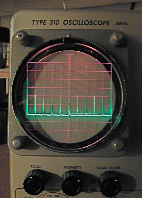
ALL digital meters have a sampling rate. The screen can not be made to change fast enough. It's not the dwell (width of the pulse) that affects the meter, it's the number of pulses per sampling rate. At higher RPM you get more pulses per sampling time. You will need a scope to see that the current is approximately the same at different RPM. They will appear as semi square waves as the module shuts on and off, all the same height, but a lot closer together.
![Image]()
1,030 posts
·
Joined 2012
I thought the only purpose of the ballast resistor on point ignitions was to reduce voltage across the points to reduce arch and increase point life. During start up the resistor is by-passed to increase voltage to the coil and increase spark voltage to help with cold starting.
On electronic ignitions, with no points to burn and wear out, reduced voltage is not necessary so they were designed to operate at battery voltage.
As far as max46 question, you do not need the ballast resistor with your HEI distributor and it may not be reducing voltage to your HEI. Check the connections on the resistor. If the HEI wire is under the same screw as the wire from the ignition switch then the resistor is not in the circuit and not reducing voltage to the HEI.
14,620 posts
·
Joined 2012
You guys are talking two different subjects at once. The ballast resistor has MUCH to do with voltage, and not much at all to do with current draw (amperage).
The resistor does reduce voltage in order to cut back on points burning, and extend the life of them. As pointed out above an HEI has no need for one, and works much better without it.
The car Max described seeing obviously had been converted over by someone to HEI. If the feed wire of the newer dist is on the same terminal as the incoming power...no problem. If the power is still run through the resistor, the dist isn't going to feed the plugs its designed full power.
31,657 posts
·
Joined 2007
I believe the original posters question has been answered in several posts and the remainder of the thread has been about ignitions in general, not a specific question. This was an old thread about HEI with a new question about Pertronix thrown in. If you don't read the entire thread, you will be answering an unrelated question.
That's the problem with adding a new question to an old post. It's confusing to anyone that doesn't read the entire thread and some threads can get into a discussion, like this one.
That's the problem with adding a new question to an old post. It's confusing to anyone that doesn't read the entire thread and some threads can get into a discussion, like this one.
672 posts
·
Joined 2007
To address the question, some people power an HEI with a relay. To do this, they'll use the original resistor wire that used to go to the points to turn the relay on and off with the ignition switch and then run a full 12 volts from the battery, through the relay, to the HEI. Since relays take very little voltage to activate and the ignition resisted wire (or wire coming from the ballast resistor) is already wired to the ignition switch, it makes a great way to power a relay.
185 posts
·
Joined 2008
I just installed an HEI distributor in my Nomad with no problems. My question is what to do with the leftover wires that went to the coil and ballast resistor? Don't want to just leave them hanging. Any ideas?
303 posts
·
Joined 2014
I learned from the best HEI guy on the planet, don't hack the looms up. When I do an HEI conversion for a customer in my shop, I simply tape up the terminals on the stock wire(s), and insert them into the wiring loom in some fashion, so they are still there, and functional if they need to be used for an emergency, or other reason.
I also never use a relay to actuate an HEI.
Willard Thompson
I also never use a relay to actuate an HEI.
Willard Thompson
2,061 posts
·
Joined 2013
Curious, why never use a relay? Some HEIs pull more current than the tri five stock system. And I have seen ignition switches overheat with an HEI dizzy if there is any corrosion on the contacts. The relay reduces current thru the ignition switch and allows you to use larger wire and shorter wire length to get the full 12 volts at max current from the battery to the HEI. This ensures max spark at the plugs.
As far as the original question, if you use ohms law, 5 amps thru a 1.8 ohm resistor, Tha resistor drops 9 volts leaving only a little over 3 volts across the HEI coil. The resistor is using 45 watts and the HEI a little over 15 watts. I know these values are a little off because it is not constant current, it is pulses. But this gives you an idea why not to use the resistor unless the HEI you are using specifically call for it.
This is not mentioned to pee on anyone's sureties, it's just my opinion and aberrations.
Take it as you will! :anim_25::shakehands::flag6:
303 posts
·
Joined 2014
I NEVER recommended using a resistor of any kind with an HEI, but, all the point replacement systems are not an HEI, plain and simple, never were, never will be.
And, if someone wants to run defective electronic components, switches, wiring, connectors, so be it for them. I choose to make sure all my customer's cars have systems that work with the draw levels and usages in place, with a buffer added for safety.
Difference is, doing it the right way, vs, doing it half-baked just plain wrong.
I've seen, fixed and had way too many relays fail over the years, don't want to create yet another problem point by using what is not needed, extra possible failure parts. Besides, most of this stuff just does not need relays to work right.
There is another topic on right now, H4 headlight bulbs dim. If we assume the H4 bulbs have the same wattage levels as the standard head light bulbs, the loading is the same, no changes needed, If the wattage load is higher, my feeling and experience tells me to boost the wiring to handle the added load, not use a relay. Less to go wrong.
Willard Thompson
303 posts
·
Joined 2014
A little bit more on why I do it the way I do.
A relay is yet another failure item in the system, fail, and, if you have run it off the resisted wire, you still cannot run the vehicle with an HEI.
Adding a dedicated HEI power wire, with no relay, no fuse, is the way to go. HEI's do not pull enough amperage to be a concern to force using a relay.
Hiding the point wire cleans up the loom, and keeps the wire in place, and active, should it need to be reused in an emergency.
Works for me.
Willard Thompson
249 posts
·
Joined 2013
HEI-MSD RTR
I saw a 56 the other day.
It had a MSD RTR distributor. The guy said all he did was remove the factory ballast resistor and solder the 2 ends of the green and brown wire together. I guess this would work no?
I saw a 56 the other day.
It had a MSD RTR distributor. The guy said all he did was remove the factory ballast resistor and solder the 2 ends of the green and brown wire together. I guess this would work no?
303 posts
·
Joined 2014
So, I read the above, and then asked that ignition guy you all love to hate, the best ignition person I have ever seen, about it.
He said to enjoy the ongoing module failures. He says he redoes a few of the Ready to Run distributors per year (he calls them 'Ready to Quit'), for just that, module failure. He pointed out that the module is soldered to the magnetic pickup, and is only an MSD item, with complete distributor disassembly needed just to get to it. He also related that those distributors, do that by the side of the road. And, when run with a stock GM resistor or resistor wire, don't make one volt more spark than without the resistor, and, they live.
I'll choose to do it the way he outlined, it works, no blow ups, no problems, but, why are people using those things in the first place? I'll leave it at that.
Willard Thompson
249 posts
·
Joined 2013
So are you saying the way I saw it wired is OK or the MSD RTR is a POS or both?
I always ran under the impression regardless of the make of electronic distributor to always run a new 10 gauge wire from 12V switched ignition to the coil POSITIVE which is where the distributor power wire is attached as well.
Agree?
I always ran under the impression regardless of the make of electronic distributor to always run a new 10 gauge wire from 12V switched ignition to the coil POSITIVE which is where the distributor power wire is attached as well.
Agree?
303 posts
·
Joined 2014
Yep, has worked for me, for over 4 decades, no problems. NOT ONE FIRE.
Thank you for the usual board sarcasm, it really helps, doesn't it.
Willard Thompson
Thank you for the usual board sarcasm, it really helps, doesn't it.
Willard Thompson
14,697 posts
·
Joined 2012
You are quite welcome. Sarcasm is my first language, sometimes I just can't help it when someone writes something that just screams for a reply like mine.
4,805 posts
·
Joined 2009
i installed the MALLORY UNI_LITE Conversion. the instructions showed 2 ways to install. one with the resistor/one without. what do ya do?:shakehands:
303 posts
·
Joined 2014
Best thing I can recommend, don't run an RTR in the first place.
Willard Thompson
Willard Thompson
14,697 posts
·
Joined 2012
Has any member of this group had a R2R go bad? Mine probably has over 25,000 miles on it with no problems.
-
?
-
?
-
?
-
?
-
?
-
?
-
?
-
?
-
?
-
?
-
?
-
?
-
?
-
?
-
?
-
?
-
?
-
?
-
?
-
?
- posts
- 2.6M
- members
- 72K
- Since
- 2005
A forum community dedicated to 1955, 1956, and 1957 Chevy owners and enthusiasts. Come join the discussion about restoration, engine swaps, reviews, performance, modifications, classifieds, troubleshooting, maintenance, and more! Open to all models including Belair, 210, 150, Sedans, and Nomads.
Top Contributors this Month
View All
Shadetree55
602 Replies
55wagoncrazy
327 Replies
hotrodg726
255 Replies


